Accelerometers
Accelerometers measure acceleration, or the rate of change of velocity. It is common for the acceleration to be reported in terms of 'g' or units of gravity 9.8 m/s^2 or 32.2 ft/s^2. All accelerometes work on the principle of a mass on a spring.
Accelerometer Type Selection By Application
The three main types of accelerometers are capacitive MEMS, piezoelectric, and piezoresistive. For low frequency (including DC or 0g) acceleration to about 16 g and less than 4 kHz, a capacitive MEMS sensor is the lowest cost. The more expensive piezoresistive accelerometer will have a higher frequency range and acceleration range than a capacitive MEMS sensor, and still measure down to 0 g (DC). The choice of accelerometer type for vibration and shock/impact is generally driven by the peak acceleration, the highest frequency to be measured, and if the frequency range goes down to 0g (DC). If the highest frequency to be measured is well below about 2 kHz, and the amplitude is less than +/- 16 g, then a capacitive MEMS accelerometer may be an option. If the vibration/shock/impact goes to 0 g (DC), then use a piezoresistive accelerometer, otherwise choose a piezoelectric accelerometer.
Capacitive MEMS Accelerometer
A capacitive MEMS accelerometer is best for slow motion / low frequency sensing and are the low cost devices mounted on a printed circuit board. Most triaxial IEPE (Integrated Electronics Piezo-Electric) accelerometers are limited to measuring signals to about 4 kHz. Resolution is typically reported as bits. For a 14-bit resolution and a range up to +/- 16 g, the measurement resolution would be (16*2)*(2^14) = 0.0020 g.
Piezoresistive Accelerometers
Piezoresistive accelerometers have a very wide bandwidth which allows these to be used for measuring short duration (high frequency) shock / impact events down to 0 Hz (DC).
Piezoelectric Accelerometers
Piezoelectric accelerometers are good for vibration measurements due to their wide bandwidth (frequency response), good sensitivity, and low noise. However, piezoelectric accelerometers are AC coupled, so they don't measure low frequency (near 0 Hz / DC) levels). Charge mode piezoelectric accelerometers are very durable, have a high impedance (requiring shielded cables), and they need a charge amplifier. Voltage mode Internal Electronic Piezoelectric (IEPE) accelerometers have a charge amplifier built into the accelerometer, and therefore need a DC power supply.
Bias Error
An accelerometer also experiences a bias error. This can be resolved by initially measuring the acceleration at rest for several seconds, calculating the average, and then using this as an offset for any subsequent readings. When the force of gravity is the offset, then the constant of 9.80665 m/s2 should be used for the offset.
Bandwidth
Bandwidth (frequency response) is the most important selection parameter. If the lower range of the bandwidth doesn't go to 0 Hz (DC response) then it won't measure gravity or slow vibrations.
Measurement Range
The range of an accelerometer needs to be carefully selected relative to the application. The smaller the range, the more sensitive the readings. Don't forget to consider the accelerometer shock survival rating.
Sensitivity
When measuring small amplitude accelerations, you need higher sensitivity in order to achieve a clean signal (high signal to noise ratio). For large amplitudes, sensitivity will be low.
Noise
Sometimes noise is reported as an RMS of the signal without any mechanical excitation. Anything measured below the RMS level will be of no use. Spectral noise may also be reported as uV/sqrt(Hz). When this is the case, multiply the RMS of the measurement bandwidth to get the nominal RMS acceleration noise of the sensor. Sometimes the noise is reported as spectral noise density for different frequency ranges.
Acceleration Signal Analysis
The sample rate for shock/impact measurement should be > 10 kHz. A Bessel or Butterworth filter is usually a good choice. Peak pseudo velocity (PV) is the primary method for analyzing and quantifying a shock event. It correlates better to damage than peak acceleration.
Vibration is typically measured with a sample rate to 5 kHz and filtered with a Butterworth filter. For rotating equipment, measuring the standard deviation of the acceleration in the time domain is the easiest way to obtain a robust metric to identify vibration changes in a system over time. Additionally, a displacement RMS is useful for identifying an imbalance in a rotating system.
Slow speed / low frequency motion can be measured with a sample rate of 1 kHz or less (10x the measured frequency).
Deriving Velocity & Displacement from Acceleration
All inertial navigation systems suffer from integration drift: small errors in the measurement of acceleration and angular velocity. When integration is performed on these measured values, those small errors compound into very large errors in velocity and position that appear as excessive noise. Filtering of the raw acceleration or angular velocity can help. Another approach is to detrend the data prior to integration.
Piezoelectric Accelerometers
Any sensor that requires a constant current power supply requires the use of low-noise cable has graphite on the shield so that any charge caused by flexing is bled off. The typical supply regulated current is 2 to 20 mA at a DC voltage level of +18 to +30 V. An ICP supply is pretty simple to make using 2 or 3 nine-volt batteries and an LM7805 configured as a constant current source. The essential properties for an op-amp used in either a charge amp or a voltage amp are extremely low leakage, and low noise. Constant current power supplies typically require a power input of 18 to 36 VDC.
Charge Amplifiers
Charge amplifiers provide impedance conversion, signal normalization, and gain adjustment.
Understanding and Implementing Charge Amplifiers for Piezoelectric Sensor Systems
How to Design Charge Amplifiers for Piezoelectric Sensors
Vibration Sensor Mounting Pads
Note that magnetic mount of accelerometer will limit measurement of vibration to 2.0 kHz. Adhesive mounting limited to measuring 2.5 to 5.0 kHz, and stud mounting can achieve > 6.0 kHz.
| Product | Features | Connections |
|---|---|---|
| AF #4097 ADXL343 accelerometer | 3-axis MEMs accel +/- 2 g (10-bit data, or +/- 512) +/- 16 g (13-bit data, or +/- 4096) User-selectable data rate (0.1 .. 3200 Hz) technical guide Arduino | CircuitPython |
SPI, I2C |
| AF #1231 ADXL345 accelerometer | +-2g, +-4g, +-8g or +-16g 13-bit resolution at 16g Data rates 10 Hz to 3200 Hz 10,000 g shock survival Board uses I2C 7-bit address 0x53 technical guide Arduino | CircuitPython |
SPI, I2C, STEMMA QT |
| AF #5374 | ADXL375 - High G Accelerometer (+-200g) Triaxial range of +/- 200 g's Bandwidth up to 1 kHz Shock event detection 10,000 g shock survival Noise 5 mg/sqrt(Hz) technical guide |
SPI, I2C, STEMMA QT |
| AF #4627 | H3LIS331 Ultra High Range Triple-Axis Accelerometer ±100g, ±200g, ±400g capability built-in and configurable high-pass and low-pass filters technical guide Seed Studio library for H3LIS331DL |
SPI, I2C, STEMMA QT |
Adafruit MSA301 Triple Axis Accelerometer - STEMMA QT / Qwiic

Low cost 3-axis accelerometer with 14-bit resolution, ±2g/±4g/±8g/±16g selectable scaling, I2C interface, interrupt output, data rate options 1 hZ to 500 Hz, 3V or 5V logic levels, and more.
Do you need help developing or customizing a IoT product for your needs? Send me an email requesting a free one hour phone / web share consultation.
The information presented on this website is for the author's use only. Use of this information by anyone other than the author is offered as guidelines and non-professional advice only. No liability is assumed by the author or this web site.
Sensors

Sensor Calibration
Sensitivity, Resolution, Response Time, etc.

50000 PPM (5%) CO2 Sensors

MQ Gas Sensors

MQ-6 LPG Gas Sensor

MQ-7 Carbon Monoxide Gas Sensor
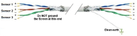
Sensor to microcontroller / data acquisition device cables

Accelerometers
IMU / Gyroscope
Magnetometer
Audio
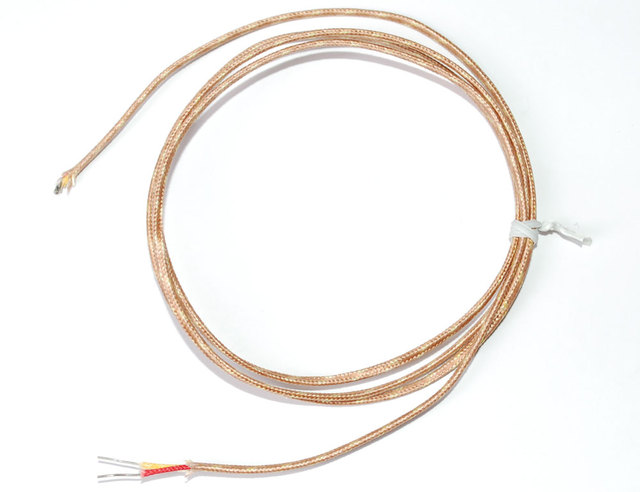
Thermocouple
AF Sensirion SHT40 Temperature & Humidity Sensor
.svg)
Motion Sensors
.png "object detection sensors")
Object Detection Sensors

Strain Gauge

Color
.png)
Pressure
Liquid Flow Meter

Operational Amplifiers
Components

Tools
Basic Components

Suppliers

VAC

XBee I/O Line Passing
xBee wireless communication modules + Arduino

I2C bus / SPI / 1-Wire
.png)
UART TTL Serial RS-232
.png)
LoRa Communications

Triac
Light Emitting Diode (LED)

NeoPixels
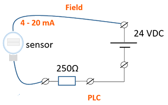
4-20 mA Current Loops
.png)
Human Health & Electrical Power
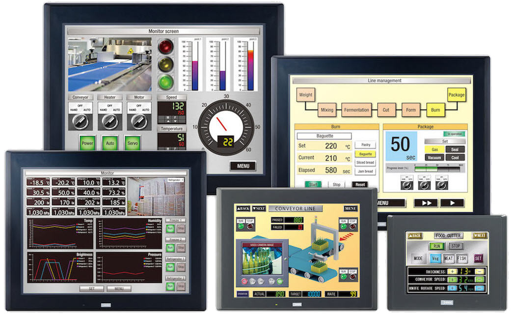
HMI
")
Mobile Apps
Hall Effect Sensor
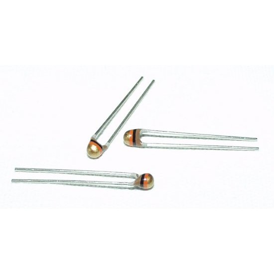
NTC Thermistor
.png "Op Amp - operational amplifier. Amplify, filter, add, manipulate analog signals.")
Amplify an Analog Signal

Offset a input signal
.png)
Electric Motors
.jpg)
Laptop 12V Power Supply

MCP2515 CAN Bus Module
.png)
TJA1050 CAN Bus Module

1.2" 4-Digit 7-Segment LED Display

Batteries

2022 Character Display Comparison
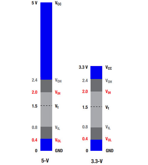
Logic Level Converter
.png)
Circuit Protection
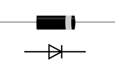
Diodes
.jpg)
PMOS / P-Channel MOSFET

Logic Level NMOS / N-Channel MOSFET
Voltage Measurement

Analog to Digital Conversion (ADC)

Variable output VDC
.png)
Turn On/Off Noisy DC Device
ADC Analog Input