MQ-7 Carbon Monoxide Gas Sensor
The MQ-7 gas sensor measures concentrations of carbon monoxide (CO).
The MQ-7 sensor heating cycle consists of 5.0V to heater for 60 sec, followed by 1.4V for 90 sec (a total cycle of 2.5 minutes). If temperature is low or humidity high, run heater on low always. Fully wet or frozen will destroy the ceramic.
After three heating cycles, the sensor output is measured prior to the end of the low power (1.4V) portion of the heating cycle.

See link at http://www.savvymicrocontrollersolutions.com/index.php?sensor=mq-gas-sensors for general information about the MQ line of gas sensors and how to make connections to them.
Background
In the United States, OSHA limits long-term workplace exposure levels above 50 ppm. The average level in homes is 0.5-5ppm. The level near properly adjusted gas stoves in homes and from modern vehicle exhaust emissions is 5-15ppm. The exhaust from automobiles in Mexico City central area is 100-200ppm. The amount of CO that can be created from the exhaust from a home wood fire is 5000ppm. Concentrations as low as 667ppm may cause up to 50% of the body's hemoglobin to convert to carboxyhemoglobin. A level of 50% carboxyhemoglobin may result in seizure, coma, and fatality.
Approach
My circuit utilizes a temperature and humidity sensor in order to provide data to permit correction of the measured output from the sensor to the standard conditions (20C 65% RH) reported by the datasheet for the relationship to concentrations of CO. A buzzer and red LED provide warning when the threshold of 50 ppm is exceeded.
Connections
If no ground, then B1 to GDD = 5.0V. With ground connection and in clean air, reading (B1 to GND) is approximately 4500 mV initially, then dropping over time (after burn-in) to 2300. The load resistor = 10 k ohms.
Sensor Measurement
The output from the sensor is a measured voltage, Vo. A load resistor RL (10 to 60 k ohms) is in series with a protection resistor (10 k ohms). We will use a load resistor of 10 k ohms. The sensor's resistance Rs and the load resistor RL form a voltage divider. The sensor output voltage is therefore related to the voltage divider rule:
Vo = RL * Vc / (Rs + RL)
Vo = output voltage
Vc = input voltage (5.0 V)
Solving for Rs:
Rs = (Vc - Vo) * (RL / Vo)
Calibration
The best way to calibrate the device is to take a measurement in an environment with a known concentration (ppm) of CO. You can buy bottles of calibrated gas with a specific concentration of CO that includes a calibration certificate for around $75 to $400. The alternative is to calibrate it in clean air (no CO present). To calibrate the sensor in clean air, measure the sensor output and then calculate the Ro value:
Ro = Rs / Ro_clean_air_factor
where Ro_clean_air_factor = 10000 ohms.
Using Rs from the voltage divider equation:
Rs = ((Vc - Vo) * RL) / Vo
Rs = sensor resistance
RL = load resistor value in ohms (10 k)
Vc is the supply voltage, 5.0 V
Vo is the output voltage measured from the sensor
Substituting Rs above into the first equation and solve:
Ro = Rs / Ro_clean_air_factor
Ro = [((Vc - Vo) * RL / Vo ]/ Ro_clean_air_factor)
Ro = [(Vc - Vo) * RL ] / (Vo * Ro_clean_air_factor)
Note that from the datasheet, at a very low concentration of 100 ppm, Rs/Ro = 1.0 @ 20 C and 65% RH (RL = 10 k ohm). Lower Rs/Ro values correspond to higher concentrations of CO.
With a calibrated value for Ro, you may now take readings of the air, calculate the value Rs from the Vo measurement, and then compare the ratio Rs/Ro to the table from the datasheet to get the CO concentration in ppm.
Rs = (Vc - Vo) * (RL / Vo)
Deriving CO concentration from the sensor reading
The data sheet provides a graph for CO concentration in ppm versus Rs/Ro for the condition of 20 C and 65% RH. If you fit a curve to the values provided, you find that:
Rs/Ro = 22.07 * (CO ppm) ^ -0.667
To solve for CO concentration, you use natural logs. Then:
CO ppm = [(Rs/Ro)/22.07]^(1/-0.0667)
You can use the above equation to determine the CO concentration from a provided Rs/Ro measured value at 20 C and 65% RH. If your measured Rs/Ro value is outside of 20 C and 65% RH, then you need to adjust your measured values to those standard conditions.
The datasheet also provides Rs/Ro for various temperatures and two relative humidity values of 33% and 85%. If you plot the values in the curves and fit a curve to them, you can derive an equation to predict the Rs/Ro values at 33% RH and 85% RH for a specified temperature.
Rs/Ro @ 33% RH = 5.93e-6*(degC)^3+5.33E-4*(degC)^2-1.82E-2*(degC)+1.02
Rs/Ro @ 85% RH = 7.413e-8*(degC)^3+1.14E+4*(degC)^2-1.14E-2*(degC)+1.03
If you interpolate between the two RH values (33% & 85%), you can determine the Rs/Ro value at 20C and 65% RH.
Do you need help developing or customizing a IoT product for your needs? Send me an email requesting a free one hour phone / web share consultation.
The information presented on this website is for the author's use only. Use of this information by anyone other than the author is offered as guidelines and non-professional advice only. No liability is assumed by the author or this web site.
Sensors

Sensor Calibration
Sensitivity, Resolution, Response Time, etc.

50000 PPM (5%) CO2 Sensors

MQ Gas Sensors

MQ-6 LPG Gas Sensor

MQ-7 Carbon Monoxide Gas Sensor
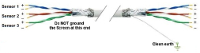
Sensor to microcontroller / data acquisition device cables

Accelerometers
IMU / Gyroscope
Magnetometer

Audio
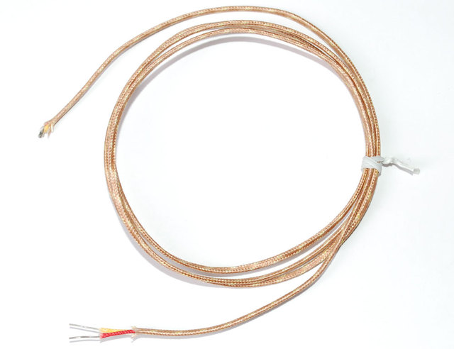
Thermocouple
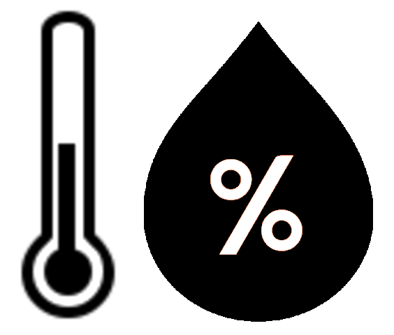
AF Sensirion SHT40 Temperature & Humidity Sensor
.svg)
Motion Sensors
.png "object detection sensors")
Object Detection Sensors

Strain Gauge

Color
.png)
Pressure
Liquid Flow Meter

Operational Amplifiers
Components

Tools
Basic Components

Suppliers

VAC

XBee I/O Line Passing
xBee wireless communication modules + Arduino

I2C bus / SPI / 1-Wire
.png)
UART TTL Serial RS-232
.png)
LoRa Communications

Triac
Light Emitting Diode (LED)

NeoPixels
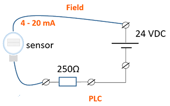
4-20 mA Current Loops
.png)
Human Health & Electrical Power
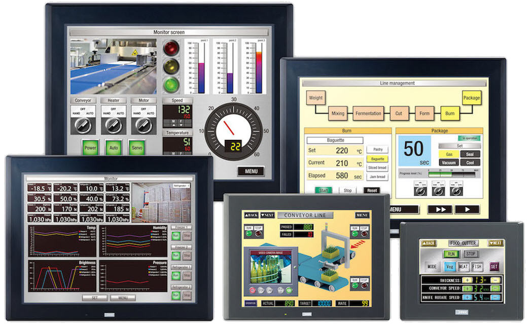
HMI
")
Mobile Apps
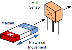
Hall Effect Sensor
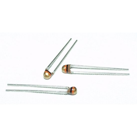
NTC Thermistor
.png "Op Amp - operational amplifier. Amplify, filter, add, manipulate analog signals.")
Amplify an Analog Signal

Offset a input signal
.png)
Electric Motors
.jpg)
Laptop 12V Power Supply

MCP2515 CAN Bus Module
.png)
TJA1050 CAN Bus Module

1.2" 4-Digit 7-Segment LED Display

Batteries

2022 Character Display Comparison
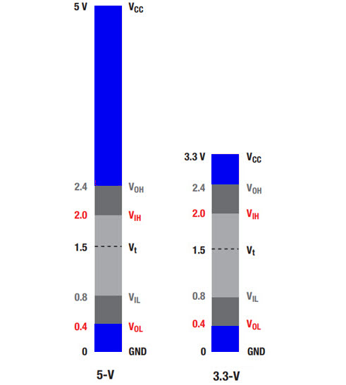
Logic Level Converter
.png)
Circuit Protection
Diodes
.jpg)
PMOS / P-Channel MOSFET

Logic Level NMOS / N-Channel MOSFET
Voltage Measurement

Analog to Digital Conversion (ADC)

Variable output VDC
.png)
Turn On/Off Noisy DC Device
ADC Analog Input