UART TTL Serial RS-232
Quick Start Guide
RS-232 is limited to a conservative distance of 15 m (50 ft), with distances to 150 m / 500 ft possible at a baud rate of 9600. RS-485 is limited to 100 kbps at 1200 m, 35 mbs @ 12m, and a maximum of 32 nodes.
Use hardware UART for the most reliable TTL / RS-232 communication between MCU devices. Examples include:
- Arduino Mega
- MCU devices with the ATSAMD21 chip such as the Arduino Zero, Adafruit Feather M0, Adafruit Trinket M0 , Adafruit Metro M0 Express
- Particle Xenon, Argon, Boron
TTL serial communications are unreliable when using the SoftwareSerial library on the Arduino Uno. Putting TTL-to-RS232 between two Uno's is poor too. The solution is to use another microcontroler (MCU) with hardware UART.
TTL to RS-232 conversion works best with the SparkFun Transceiver Breakout - MAX3232 BOB-11189, SparkFun RS232 Shifter - SMD
The breadboard layout below implements a successful TTL-to-RS232-to-TTL conversion and communcation using the SparkFun Transceiver Breakout - MAX3232 BOB-11189

The DTE (data terminal equipment) is typically the computer end, and the DCE (data circuit-terminating equipment or data communication equipment) is the connected device such as a modem.
.png "click to see larger image")
Hardware UART MCU Options
Arduino Mega 2560 has 4x hardware 4X hardware UARTs:
- Serial D1/TX0 D0/TX0 (USB connection for programming)
- Serial1 D18/TX1 & D19/RX1,
- Serial2 D16/TX2 & D17/RX2
- Serial3 D14/TX3 & D15/RX3
Using ATSAMD21 SERCOM for more SPI, I2C and Serial ports
ATSAMD21
The ATSAMD21 chip in the Arduino Zero, Adafruit Feather M0, Adafruit Trinket M0 , Adafruit Metro M0 Express has 6 'SERCOM's (SERial COMmunication modules). Each of these SERCOMs can be used for I2c, SPI, or Serial. Available on both Zero's and Feathers, you can use pins 10, 11, 12 and 13 for SERCOM 1.
SERCOM 1
Pin	Arduino 'Pin'	SERCOM		SERCOM alt
-----------------------------------------
PA18	D10		SERCOM1.2	SERCOM3.2
PA16	D11		SERCOM1.0	SERCOM3.0
PA19	D12		SERCOM1.3	SERCOM3.3
PA17	D13		SERCOM1.1	SERCOM3.1

// Configure D10 be TX and D11 be RX
#include    // required before wiring_private.h
#include "wiring_private.h" // pinPeripheral() function

Uart Serial2 (&sercom1, 11, 10, SERCOM_RX_PAD_0, UART_TX_PAD_2);
void SERCOM1_Handler()
{
  Serial2.IrqHandler();
}

void setup() {
  Serial.begin(115200);

  Serial2.begin(115200);

  // Assign pins 10 & 11 SERCOM functionality
  pinPeripheral(10, PIO_SERCOM);
  pinPeripheral(11, PIO_SERCOM);
}

uint8_t i=0;
void loop() {
  Serial.print(i);
  Serial2.write(i++);
  if (Serial2.available()) {
    Serial.print(" -> 0x"); Serial.print(Serial2.read(), HEX);
  }
  Serial.println();

  delay(10);
}
SERCOM 2
Pin	Arduino 'Pin'	SERCOM		SERCOM alt
-----------------------------------------
PA14	D2		SERCOM2.2	SERCOM4.2
PA09	D3		SERCOM0.1	SERCOM2.1
PA08	D4		SERCOM0.0	SERCOM2.0
PA15	D5		SERCOM2.3	SERCOM4.3

// TX on D4 (SERCOM2.0) and RX on D3 (SERCOM2.1)
#include    // required before wiring_private.h
#include "wiring_private.h" // pinPeripheral() function

Uart Serial2 (&sercom2, 3, 4, SERCOM_RX_PAD_1, UART_TX_PAD_0);
void SERCOM2_Handler()
{
  Serial2.IrqHandler();
}

void setup() {
  Serial.begin(115200);

  Serial2.begin(115200);

  // Assign pins 3 & 4 SERCOM functionality
  pinPeripheral(3, PIO_SERCOM_ALT);
  pinPeripheral(4, PIO_SERCOM_ALT);
}

uint8_t i=0;
void loop() {
  Serial.print(i);
  Serial2.write(i++);
  if (Serial2.available()) {
    Serial.print(" -> 0x"); Serial.print(Serial2.read(), HEX);
  }
  Serial.println();

  delay(10);

}
Feather M0 SERCOM 5
Pin	Arduino 'Pin'	SERCOM		SERCOM alt
-----------------------------------------
PA20	D6		SERCOM5.2	SERCOM3.2
PA21	D7		SERCOM5.3	SERCOM3.3
PB02	A5				SERCOM5.0
PA22	D20 / SDA	SERCOM3.0	SERCOM5.0
PA23	D21 / SCL	SERCOM3.1	SERCOM5.1
SAMD51
Serial TX on PAD 0 only.
Particle Xenon
Second hardware UART is on pins D4 (Tx), and D5 (Rx). CST on pin D6, and RTS on pin D8.
Examples
Feather M0 Basic to Arduino Uno

Feather M0
/*
  Adafruit Feather M0 Basic Proto - ATSAMD21 Cortex M0

  AF_Feather_M0_Basic_UART2.ino

  Tx & Rx via UART2

*/

//////////////////////////////////////////////////////////////////////////////
#include <Arduino.h>   // required before wiring_private.h
#include "wiring_private.h" // pinPeripheral() function

Uart Serial2 (&sercom1, 11, 10, SERCOM_RX_PAD_0, UART_TX_PAD_2);
void SERCOM1_Handler()
{
  Serial2.IrqHandler();
}


// M0  (Feather M0)
const byte pinBuiltInLED = 13;
byte stateBuiltInLED = LOW;

void blinkERR(byte ledPIN){
  // S-O-S
  const int S = 150, O = 300;
  for(int i = 3; i>0; i--){
    digitalWrite(ledPIN, HIGH);
    delay(S);
    digitalWrite(ledPIN, LOW);
    delay(S);
  }
  delay(200);
  for(int i = 3; i>0; i--){
    digitalWrite(ledPIN, HIGH);
    delay(O);
    digitalWrite(ledPIN, LOW);
    delay(O);
  }
  delay(200);
  for(int i = 3; i>0; i--){
    digitalWrite(ledPIN, HIGH);
    delay(S);
    digitalWrite(ledPIN, LOW);
    delay(S);
  }
  delay(200);
} // blinkERR()

const unsigned long timerInterval = 500;
unsigned long timerLast = 0;  // timer

byte valToTx = 5;

//////////////////////////////////////////////////////////////////////////////
// Show serial messages when DEBUG = true, otherwise minimize them.
// WARNING:   The Feather M0 will not begin script execution e.g. setup() & loop()
//            until the serial monitor is loaded if serial ouput is enabled.
//            For this reason, wrap serial output around a DEBUG check.
#define DEBUG true
//////////////////////////////////////////////////////////////////////////////

void setup() {

  pinMode(pinBuiltInLED, OUTPUT);

  #if DEBUG
  Serial.begin(9600);
  while (!Serial) {
    digitalWrite(pinBuiltInLED, HIGH);
    delay(100);
  }
  digitalWrite(pinBuiltInLED, LOW);
  Serial.println("Serial ready");
  #endif

  // Configure UART2
  Serial2.begin(9600);
  while (!Serial2) {
    digitalWrite(pinBuiltInLED, HIGH);
    delay(100);
  }
  digitalWrite(pinBuiltInLED, LOW);
  // Assign pins 10 & 11 SERCOM functionality
  pinPeripheral(10, PIO_SERCOM);
  pinPeripheral(11, PIO_SERCOM);

} // setup()


void loop() {

  if (timerLast > millis())  timerLast = millis();
  if ((millis() - timerLast) > timerInterval) {
    valToTx = valToTx + 5;
    if (valToTx > 250) {
      valToTx = 0;
    }
    // Tx the count int value via Serial2
    // Note: Serial.write() sends bytes to the serial port
    //       Serial.print() sends ASCII characters
    Serial2.write(valToTx);
    //Serial.print("\nTx: ");
    //Serial.println(valToTx);
    if (stateBuiltInLED == LOW) {
      stateBuiltInLED = HIGH;
    } else {
      stateBuiltInLED = LOW;
    }
    timerLast = millis();
  }

  digitalWrite(pinBuiltInLED, stateBuiltInLED);

  // Write anything received on Serial2 to the Arduino
  // IDE serial monitor.
  if (Serial2.available()) {
    char c = Serial2.read();
    if (valToTx != c) {
      Serial.print("\nTx: ");
      Serial.println(valToTx);
      Serial.print("Rx: ");
      Serial.println(c);
    }
  }

} // loop()
Arduino Uno
/*

  RS-232 / TTL Rx by Arduino Uno

  proj_MI_GP50sensorReZero_0.6.0_Uno_SerialSoftRx.ino

    LED on pin 13 toggled
    Basic interval timer
    Compile time debug option

    In Arduino IDE:
      Set board to 'Arduino Uno'
      Set programmer to 'AVRISP mkii'
      Set COM port

  Wiring:
    Uno Tx -> T1IN  --- T1OUT -> R1IN   --- R1OUT -> Uno Rx
             |Logic --- RS232|   |RS232 --- Logic|

*/

/////////////////////////////////////////////////////////////////////////
const byte pinBuiltInLED = 13;
byte stateBuiltInLED = LOW;
/////////////////////////////////////////////////////////////////////////

void blinkERR(byte ledPIN){
  // S-O-S
  const int S = 150, O = 300;
  for(int i = 3; i>0; i--){
    digitalWrite(ledPIN, HIGH);
    delay(S);
    digitalWrite(ledPIN, LOW);
    delay(S);
  }
  delay(200);
  for(int i = 3; i>0; i--){
    digitalWrite(ledPIN, HIGH);
    delay(O);
    digitalWrite(ledPIN, LOW);
    delay(O);
  }
  delay(200);
  for(int i = 3; i>0; i--){
    digitalWrite(ledPIN, HIGH);
    delay(S);
    digitalWrite(ledPIN, LOW);
    delay(S);
  }
  delay(200);
} // blinkERR()

////////////////////////////////////////////////////////////////
// SoftwareSerial

#include <SoftwareSerial.h>
// 8,7 recommended for Uno or 328P
byte pinRx = 8;
byte pinTx = 7;
// SoftwareSerial(rxPin, txPin, inverse_logic)
SoftwareSerial SoftSerial(pinRx,pinTx,false); //Rx, Tx


void setup () {
  pinMode(pinBuiltInLED, OUTPUT);

  // setup software serial
  pinMode(pinRx, INPUT);
  pinMode(pinTx, OUTPUT);
  SoftSerial.begin(9600);
  while (!SoftSerial) {
    digitalWrite(pinBuiltInLED, HIGH);
    delay(100);
  }
  digitalWrite(pinBuiltInLED, LOW);

  Serial.begin(9600);
  while (!Serial) {
    digitalWrite(pinBuiltInLED, HIGH);
    delay(100);
  }
  digitalWrite(pinBuiltInLED, LOW);
  Serial.println("\nSerial ready");

} // setup()


void loop() {

  // Write anything received by SoftSerial to
  // Arduino IDE serial monitor AND SoftSerial
  if (SoftSerial.available()) {
    char c = SoftSerial.read();
    Serial.write(c);
    SoftSerial.write(c);
    if (stateBuiltInLED == HIGH){
      stateBuiltInLED = LOW;
    } else {
      stateBuiltInLED = HIGH;
    }
  }

  digitalWrite(pinBuiltInLED, stateBuiltInLED);

} // loop()
Do you need help developing or customizing a IoT product for your needs? Send me an email requesting a free one hour phone / web share consultation.
The information presented on this website is for the author's use only. Use of this information by anyone other than the author is offered as guidelines and non-professional advice only. No liability is assumed by the author or this web site.
Sensors

Sensor Calibration
Sensitivity, Resolution, Response Time, etc.

50000 PPM (5%) CO2 Sensors

MQ Gas Sensors

MQ-6 LPG Gas Sensor

MQ-7 Carbon Monoxide Gas Sensor
Sensor to microcontroller / data acquisition device cables

Accelerometers
IMU / Gyroscope
Magnetometer

Audio
Thermocouple

AF Sensirion SHT40 Temperature & Humidity Sensor
.svg)
Motion Sensors
.png "object detection sensors")
Object Detection Sensors

Strain Gauge

Color
.png)
Pressure
Liquid Flow Meter

Operational Amplifiers
Components

Tools
Basic Components

Suppliers

VAC

XBee I/O Line Passing
xBee wireless communication modules + Arduino
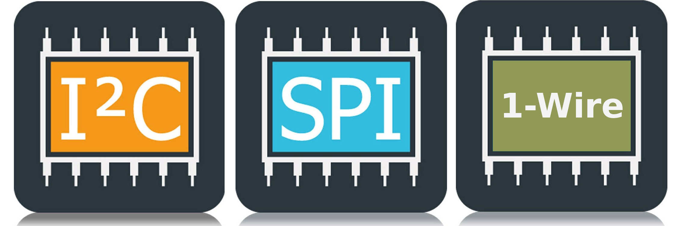
I2C bus / SPI / 1-Wire
.png)
UART TTL Serial RS-232
.png)
LoRa Communications

Triac
Light Emitting Diode (LED)

NeoPixels
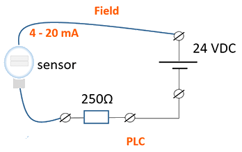
4-20 mA Current Loops
.png)
Human Health & Electrical Power
HMI
")
Mobile Apps
Hall Effect Sensor
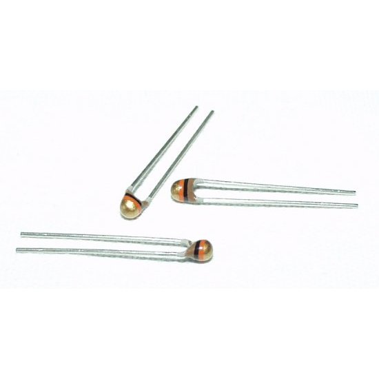
NTC Thermistor
.png "Op Amp - operational amplifier. Amplify, filter, add, manipulate analog signals.")
Amplify an Analog Signal

Offset a input signal
.png)
Electric Motors
.jpg)
Laptop 12V Power Supply

MCP2515 CAN Bus Module
.png)
TJA1050 CAN Bus Module

1.2" 4-Digit 7-Segment LED Display

Batteries

2022 Character Display Comparison
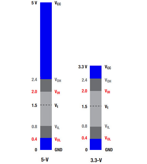
Logic Level Converter
.png)
Circuit Protection
Diodes
.jpg)
PMOS / P-Channel MOSFET

Logic Level NMOS / N-Channel MOSFET
Voltage Measurement

Analog to Digital Conversion (ADC)

Variable output VDC
.png)
Turn On/Off Noisy DC Device
ADC Analog Input