Sensitivity, Resolution, Response Time, etc.
A sensor's sensitivity indicates how much its output changes when the input quantity it measures changes. Some sensors can also affect what they measure.
Precision measures the sensor output relative to the input.
Most sensors have a time constant that reflects the amount of time it takes for the sensor to get to 63% of the final value when exposed to a step change. The sensor response time is five times (5x) the Time Constant. The Response Time is the time it takes for a sensor to reach 99.3% of the total step change in the measured values. The sensor Response Time should be less than whatever change the sensor is attempting to measure. Your sensor response time needs to be less than the smallest interval of change you are attempting to measure.
Hysteresis error causes the output to vary depending on the previous input values, the sequence of increasing or decreasing values, or the position in the sensor's full scale range.
Accuracy is the amount of uncertainty in a measurement relative to an absolute standard. Typically defined in terms of gain and offset. Offset errors are given in the unit of the sensor measurement and are independent of the magnitude of the input signal. Gain error depend on the magnitude of the input signal and are expressed as a percentage of the sensor full scale value. Example: Accuracy = +/- (0.1% of input + 1 mV)
Resolution is the smallest change that can be detected in the quantity that is being measured. It can be expressed as either the ratio of the maximum signal measured to the smallest part that can be resolved, or the amount of change that can be detected, expressed as the number of bits (A/D converter bits).
The Characteristic Curve defines the sensor's response to an input in terms of an offset, sensitivity or slope, and linearity.
Linearity, Repeatability, Hysteresis, and Accuracy
The calculation of accuracy, repeatability, hysteresis, and linearity should be straight forward, but it is not for two of these items. The International Electrotechnical Commission's (IEC) provides well defined information, but the method for the calculation of accuracy is not specified, and the calculation methods employed for linearity vary considerably from one sensor supplier to another. It is critical that you carefully review how these are calculated before making judgements about the suitability of a sensor for your application.
Linearity
The output of the transducer over it’s full span is measured and plotted with a linear regression line. The three most common linearity trend lines applied are terminal point, best fit straight line (BFSL), and zero-based best fit straight line (see IEC 61298-2) . I implemented the BFSL method, which does not require the line to pass through the zero or span points.

The linearity error is the maximum deviation of the sensor output from the BFSL. It may be expressed as an absolute value, or as a percentage of the full scale value.
Hysteresis
Hysteresis is the difference in measured sensor values at points within the same cycle from 0 to full scale and zero again. Those points within a cycle are typically specified as a percentage of the full scale value. The total hysteresis error is the maximum hysteresis error calculated for every point measured across the full span of the sensor.

Repeatability
Repeatability is the variation of a measured sensor value at the same point within a cycle, in the same direction, across multiple cycles. The direction referes to if the sensor is exposed to an input from zero to full scale, or from full scale to zero.

Calculation example:
Range @ 60% of FS for 0 to FS from cycle 1 to N = Range(112.9-112.8) = 0.010
Range @ 60% of FS for FS to 0 from cycle 1 to N = Range(111.7-111.6) = 0.010
(repeat calculation of range for 0%, 20%, 40%, 80%, 100%)
Repeatability = max range value for the points evaluated (0%, 20%, 40%, 80%, 100%) = 0.010 mm
% repeatability = 100 * (max range value) / span = 100 * 0.010 / 188.0 = 0.0053%
Accuracy
Accuracy is a composite of the error due to hysteresis, repeatability, and linearity. IEC 61298-2 states that accuracy must include hysteresis, non-repeatability and non-linearity, but it does not state how it should be calculated. The formula below is the method utilized here.

Sensor Data Packets
An unencrypted signed floating point value with six significant digits and a RFC3339 date/time stamp consumes 31 bytes (Ex. "20200216T150644Z;+6.534755E+06").
GPS latitude and longitude coordinates may be limited to 5 decimal places, achieving an accuracy to 1.11 meters at the equator. Four decimal places is accurate to 11.1 meters. Six decimal places is accurate to 0.111 meters. Latitude range is +/- 90 degrees. Longitude is +/- 180 degrees.
Related Links
Accuracy, Precision, Resolution, and Sensitivity
Do you need help developing or customizing a IoT product for your needs? Send me an email requesting a free one hour phone / web share consultation.
The information presented on this website is for the author's use only. Use of this information by anyone other than the author is offered as guidelines and non-professional advice only. No liability is assumed by the author or this web site.
Sensors
Sensor Calibration
Sensitivity, Resolution, Response Time, etc.

50000 PPM (5%) CO2 Sensors

MQ Gas Sensors

MQ-6 LPG Gas Sensor

MQ-7 Carbon Monoxide Gas Sensor
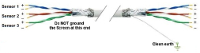
Sensor to microcontroller / data acquisition device cables

Accelerometers
IMU / Gyroscope
Magnetometer
Audio
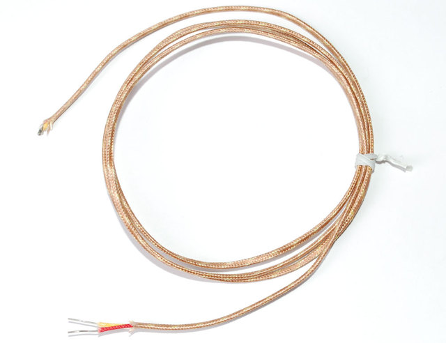
Thermocouple
AF Sensirion SHT40 Temperature & Humidity Sensor
.svg)
Motion Sensors
.png "object detection sensors")
Object Detection Sensors

Strain Gauge

Color
.png)
Pressure
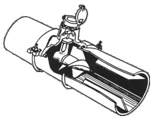
Liquid Flow Meter

Operational Amplifiers
Components

Tools
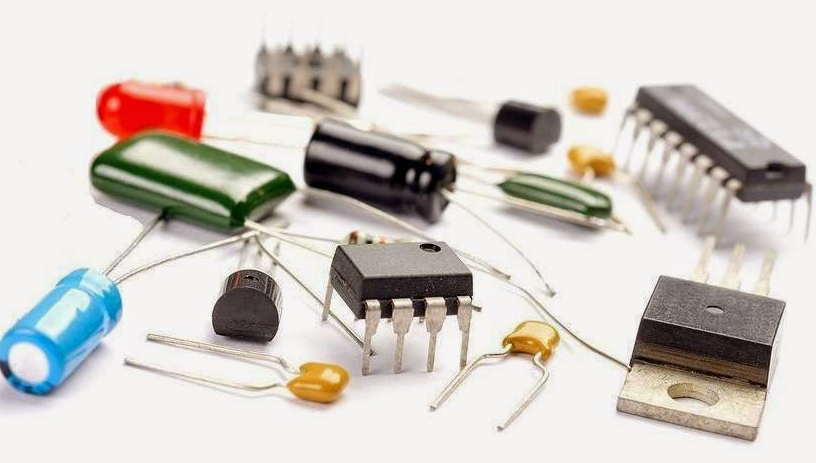
Basic Components

Suppliers

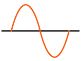
VAC

XBee I/O Line Passing
xBee wireless communication modules + Arduino

I2C bus / SPI / 1-Wire
.png)
UART TTL Serial RS-232
.png)
LoRa Communications

Triac
Light Emitting Diode (LED)

NeoPixels
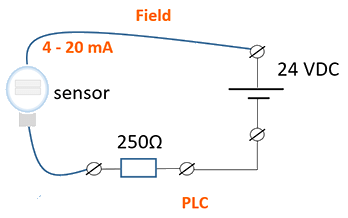
4-20 mA Current Loops
.png)
Human Health & Electrical Power
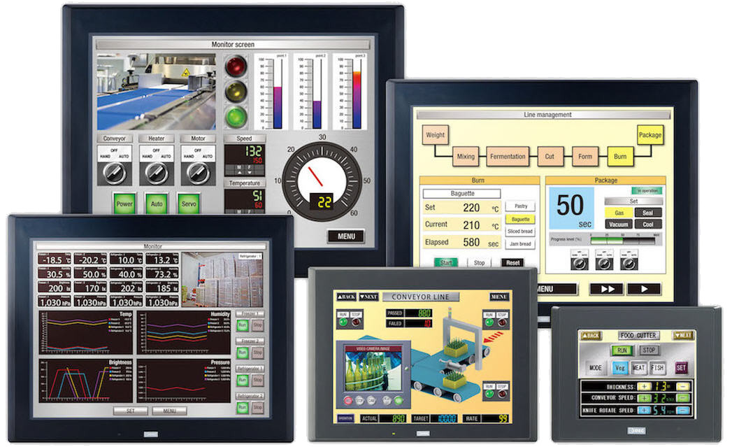
HMI
")
Mobile Apps
Hall Effect Sensor
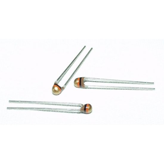
NTC Thermistor
.png "Op Amp - operational amplifier. Amplify, filter, add, manipulate analog signals.")
Amplify an Analog Signal

Offset a input signal
.png)
Electric Motors
.jpg)
Laptop 12V Power Supply

MCP2515 CAN Bus Module
.png)
TJA1050 CAN Bus Module

1.2" 4-Digit 7-Segment LED Display

Batteries

2022 Character Display Comparison
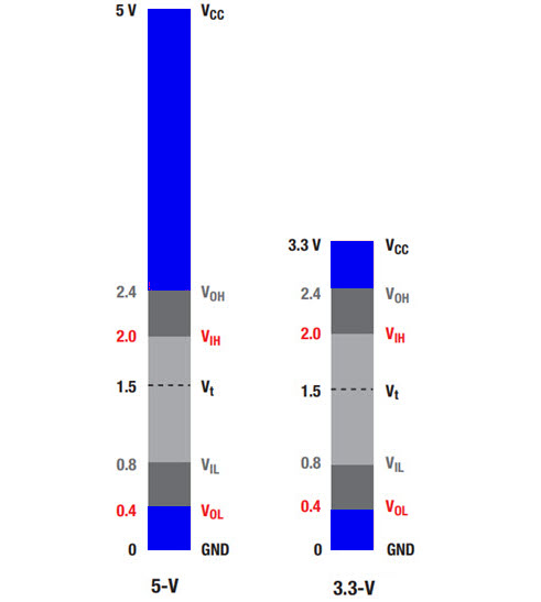
Logic Level Converter
.png)
Circuit Protection
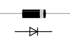
Diodes
.jpg)
PMOS / P-Channel MOSFET

Logic Level NMOS / N-Channel MOSFET
Voltage Measurement

Analog to Digital Conversion (ADC)

Variable output VDC
.png)
Turn On/Off Noisy DC Device
ADC Analog Input