PMOS / P-Channel MOSFET
Logic Level PMOS
Summary
Orient the P-Channel MOSFET (PMOS) in a circuit so that the drain pin (D) is connected to the supply positive, and the source pin (S) is connected to the load positive. Voltage up to the Vdss Drain-Source Voltage and current up to the lesser of the Id Drain Current and the Is Maximum Continuous Drain-Source Diode Forward Current will be conducted from the drain to the source when the PMOS gate pin sees a voltage more negative than the 'On Characteristic' Vgs(th) Gate Threshold Voltage maximum value. Reverse voltages greater than the Vsd Drain-Source Diode Forward Voltage value (the more negative value when looking at the difference of Vg and Vd) will be blocked by the built-in body diode. Use it to add reverse polarity protection, or to switch high side loads up to 60V @ 20 A.
Detailed Explanation
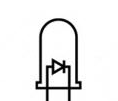
Pay careful attention to the orientation of the PMOS in a circuit. A PMOS has a body diode that conducts current under forward-bias conditions (current traveling from the drain to the source).
.jpg "click to see larger image")
The FQP27P06 PMOS for example, has a maximum Drain-Source Diode Forward Voltage (Vsd) of -4 V, and a Maximum Continuous Drain-Source Diode Forward Current of -27 A. Any reverse voltage more negative than -4 V won't be conducted from the drain to the source (source +, drain -) due to this diode. For example, in a reverse polarity situation where the drain is connected to ground and the source is connected to +4 VDC or more (properly stimulating the PMOS gate), the result will be no current flow between the PMOS source and drain pins (but it would for +3.3 V at the source).
The FQP27P06 PMOS Vgs(th) gate threshold voltage is rated at -2.0 minimum and -4.0 V maximum. This means that the difference of the gate voltage and the drain must be more negative than -4.0 V in order for the PMOS to conduct current flow from the drain to the source. For a 5 VDC power supply with the + connected to the PMOS drain and a 10 kOhm resistor pulling the PMOS gate to ground, the difference of the gate voltage relative to the drain would be Vg - Vd = 0.0 V - 4.99 V = -4.99 V (-4.99 V because of the 10 kOhm resistor and the small 0.07 ohm resistance of the PMOS in the circuit). Note that since the gate threshold voltage is -2.0 V minimum, and -4.0 V maximum, a voltage of -3.3V at the gate is not recommended for reliable stimulation of the gate.
The TP2535 has a Vgs th - Gate-Source Threshold Voltage of 2.4V and therefore can provide reverse polarity protection down to 3.3 V.
Reverse Polarity Protection Application Example
_bb.png "click to see larger image")
High Side Switching Application
The two circuits below us a N-Channel MOSFET (NMOS) to control the gate of a P-Channel MOSFET (PMOS). The gate on the NMOS is controled by a 3.3 or 5V logic microcontroller and only demands about 2 mA of current from the MCU digital output. The PMOS can switch up to 60 VDC @ 20 A (with proper heat sink).


Do you need help developing or customizing a IoT product for your needs? Send me an email requesting a free one hour phone / web share consultation.
The information presented on this website is for the author's use only. Use of this information by anyone other than the author is offered as guidelines and non-professional advice only. No liability is assumed by the author or this web site.
Sensors
Sensor Calibration
Sensitivity, Resolution, Response Time, etc.

50000 PPM (5%) CO2 Sensors

MQ Gas Sensors

MQ-6 LPG Gas Sensor

MQ-7 Carbon Monoxide Gas Sensor
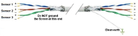
Sensor to microcontroller / data acquisition device cables

Accelerometers
IMU / Gyroscope
Magnetometer

Audio
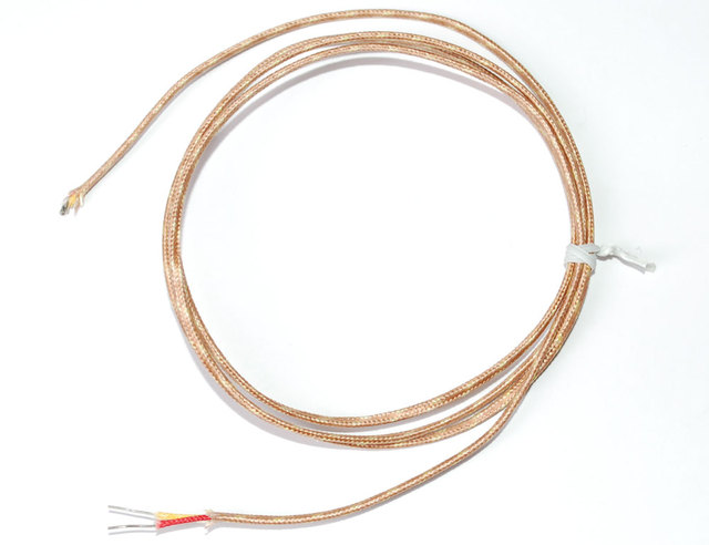
Thermocouple
AF Sensirion SHT40 Temperature & Humidity Sensor
.svg)
Motion Sensors
.png "object detection sensors")
Object Detection Sensors

Strain Gauge

Color
.png)
Pressure
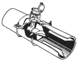
Liquid Flow Meter

Operational Amplifiers
Components

Tools
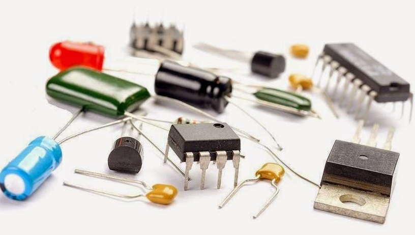
Basic Components

Suppliers

VAC

XBee I/O Line Passing
xBee wireless communication modules + Arduino
I2C bus / SPI / 1-Wire
.png)
UART TTL Serial RS-232
.png)
LoRa Communications

Triac
Light Emitting Diode (LED)

NeoPixels
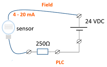
4-20 mA Current Loops
.png)
Human Health & Electrical Power
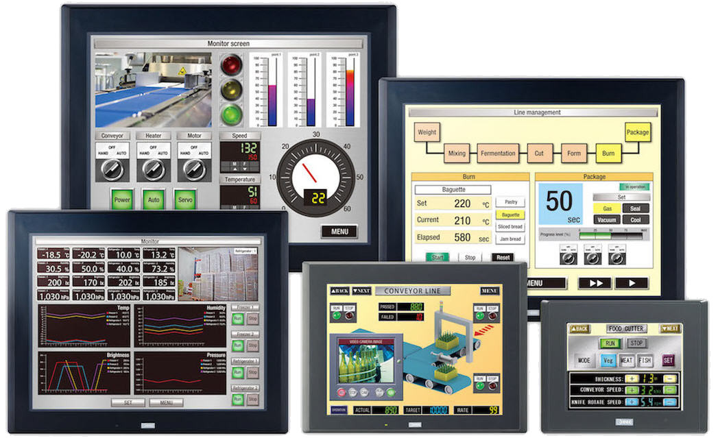
HMI
")
Mobile Apps
Hall Effect Sensor
NTC Thermistor
.png "Op Amp - operational amplifier. Amplify, filter, add, manipulate analog signals.")
Amplify an Analog Signal

Offset a input signal
.png)
Electric Motors
.jpg)
Laptop 12V Power Supply

MCP2515 CAN Bus Module
.png)
TJA1050 CAN Bus Module

1.2" 4-Digit 7-Segment LED Display

Batteries

2022 Character Display Comparison
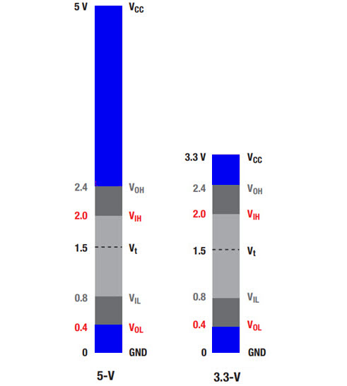
Logic Level Converter
.png)
Circuit Protection
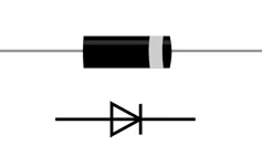
Diodes
PMOS / P-Channel MOSFET

Logic Level NMOS / N-Channel MOSFET
Voltage Measurement

Analog to Digital Conversion (ADC)

Variable output VDC
.png)
Turn On/Off Noisy DC Device
ADC Analog Input