TJA1050 CAN Bus Module
.png "click to see larger image")
The TJA1050 CAN Bus Module allows you to send data back and forth between a sensor with serial output or a sensor + microcontroller to another microcontroller 250 m / 820 ft away in a noisy environment via CAN bus. The CAN bus node receiving the message can be another TJA1050 CAN Bus Module connected to the serial port of a microcontroller.
NOTE: Microcontroller 5V logic level serial Tx and Rx pins are required to communicate with this CAN bus module.
The TJA1050 CAN Bus Module is based on the TJA1050 chip. It is fully compliant with ISO 898 standard. 5V power input +/- 5 %. The TJA1050 is the successor to the PCA82C250 high-speed CAN transceiver. Current consumption is 5 to 50 mA.
High-speed mode is the normal operating mode. The S pin internal pull-down achieves the default high-speed mode. When the pin "S" is pulled high, it will enter silent mode, disabling the transmitter. The "S" pin is not accessible on the CAN Bus Transceiver Module and is a feature specific to the TJA1050 chip.
Each transceiver has a 120 ohm resistor at the CAN bus termination. Therefore, one each of TJA1050 CAN Bus Module should be at the extreme ends of the CAN bus (wiring), and any additional CAN nodes added in series should NOT have a 120 ohm termination resistor.
Logic level for Tx & Rx pins is 5V. Tx input data will be sent to the CAN bus line. CAN data received from the CAN bus will be output to the Rx pin.
Proto Supplies product page and tutorial
The TJA1050 CAN Bus Module will transmit a serial (UART) message input at it's Rx 5V logic port and send it out over the CAN bus. A matching TJA1050 CAN Bus Module will receive the CAN message and will output it to the serial Tx 5V logic port. You don't need to use the TJA1050 CAN Bus Module for both the CAN bus sending and receiving nodes. HOWEVER, you cannot use more than two TJA1050 CAN Bus Module on the same CAN bus because it is not possible to disable the 120 ohm termination resistor built-in to each TJA1050 CAN Bus Module. These devices are best suited for one-to-one communication over a distance in a noisy environment (via CAN bus), such as between a sensor and a microcontroller.

Sender (Tx)
/*
  Adafruit Feather HUZZA ESP8266

  Confugred as SoftwareSerial "sender".

  Connect GPIO 13 and 15 on the "sender" to the
  same on the "receiver". The Tx/Rx line swap is
  done at the "receiver" SoftwareSerial declaration.

  Tx at 1 ms or 1 kHz tested and confirmed (two CAN nodes).

*/

// In Arduino IDE choose:
//  Board: Adafruit Feather HUZZAH ESP8266
//  CPU Frequency: 80 MHz
//  Flash size: 4 M (3M SPIFFS)
//

/////////////////////////////////////////////////////////////////////////
const byte pinBuiltInRedLED = 0;  // reverse wired, LOW turns LED on
const byte pinBuiltInBlueLED = 2; // reverse wired, LOW turns LED on

void blinkLED(byte ledPIN){
  //  consumes 300 ms.
  for(int i = 5; i>0; i--){
    digitalWrite(ledPIN, LOW);
    yield();
    delay(30);
    digitalWrite(ledPIN, HIGH);
    yield();
    delay(30);
  }
} //blinkLED()

/////////////////////////////////////////////////////////////////////////

#include <SoftwareSerial.h>
// NOTE: GPIO #15, is also used to detect boot-mode.
// It has a pulldown resistor connected to it, so make
// sure this pin isn't pulled high on startup (or receiving
// serial data).
// SoftwareSerial(rxPin, txPin, inverse_logic)
SoftwareSerial softSerial(14,12);

//////////////////////////////////////////////////////////////////////////////
// TimerA
// 10000000 us = 10000 ms = 10 sec = 0.1 Hz
// 1000000 us = 1000 ms = 1 sec = 1 Hz
// 100000 us = 100 ms = 0.1 sec = 10 Hz
// 10000 us = 10 ms = 0.01 sec = 100 Hz
// 1000 us = 1 ms = 0.001 sec = 1 kHz
const unsigned long timerAinterval = 100;
unsigned long timerAlap = millis();  // timer

void timerA() {
  //  Timer A
  if (timerAlap > millis())  timerAlap = millis();
  if (millis() - timerAlap > timerAinterval) {
    // do something here every timerAinterval
    digitalWrite(pinBuiltInBlueLED, LOW);
    softSerial.println(millis());
    //Serial.println(millis());
    timerAlap = millis(); // reset the timer
  } else {
    digitalWrite(pinBuiltInBlueLED, HIGH);
  }
} // timerA()


void setup() {

  Serial.begin(115200);
  while (!Serial) {
    delay(1);
  }
  Serial.println("\nSerial ready");

  softSerial.begin(9600);

  pinMode(pinBuiltInRedLED, OUTPUT);
  digitalWrite(pinBuiltInRedLED, HIGH);

  pinMode(pinBuiltInBlueLED, OUTPUT);
  digitalWrite(pinBuiltInBlueLED, HIGH);


  Serial.println("Setup complete"); Serial.println("");
} // setup()

void loop() {

  // Use yield() in any loop that will delay execution.
  // This gives ESP8266 time to do it's own housekeeping.
  //yield();

  timerA();

} // loop()
Receiver (Rx)
/*
  Adafruit Feather HUZZA ESP8266

  Configured as SoftwareSerial "receiver".
  NOTE: Cannot upload sketch while the GPIO pin #15 is
  connected to the "sender" and the "sender" is sending data.
  This is because GPIO #15, is also used to detect boot-mode.
  Must disconnect GPIO #15 until upload is complete.

  Connect GPIO 13 and 15 on the "sender" to the
  same on the "receiver". The Tx/Rx line swap is
  done at the "receiver" SoftwareSerial declaration.

*/

// In Arduino IDE choose:
//  Board: Adafruit Feather HUZZAH ESP8266
//  CPU Frequency: 80 MHz
//  Flash size: 4 M (3M SPIFFS)
//

/////////////////////////////////////////////////////////////////////////
const byte pinBuiltInRedLED = 0;  // reverse wired, LOW turns LED on
const byte pinBuiltInBlueLED = 2; // reverse wired, LOW turns LED on

void blinkLED(byte ledPIN){
  //  consumes 300 ms.
  for(int i = 5; i>0; i--){
    digitalWrite(ledPIN, LOW);
    delay(30);
    yield();
    digitalWrite(ledPIN, HIGH);
    delay(30);
    yield();
  }
} //blinkLED()

/////////////////////////////////////////////////////////////////////////

#include <SoftwareSerial.h>
// NOTE: GPIO #15, is also used to detect boot-mode.
// It has a pulldown resistor connected to it, so make
// sure this pin isn't pulled high on startup (or receiving
// serial data).
// SoftwareSerial(rxPin, txPin, inverse_logic)
SoftwareSerial softSerial(14,12);

void setup() {

  Serial.begin(115200);
  while (!Serial) {
    delay(1);
  }
  Serial.println("\nSerial ready");

  softSerial.begin(9600);

  pinMode(pinBuiltInRedLED, OUTPUT);
  digitalWrite(pinBuiltInRedLED, HIGH);

  pinMode(pinBuiltInBlueLED, OUTPUT);
  digitalWrite(pinBuiltInBlueLED, HIGH);


  Serial.println("Setup complete"); Serial.println("");
} // setup()

void loop() {

  // The built in blue LED will briefly flash on when serial data
  // is received via softSerial.
  if (softSerial.available()) {
    Serial.write(softSerial.read());
    //blinkLED(pinBuiltInBlueLED);
    digitalWrite(pinBuiltInBlueLED, LOW);
  } else {
    digitalWrite(pinBuiltInBlueLED, HIGH);
  }

  // Use yield() in any loop that will delay execution.
  // This gives ESP8266 time to do it's own housekeeping.
  //yield();

} // loop()
Do you need help developing or customizing a IoT product for your needs? Send me an email requesting a free one hour phone / web share consultation.
The information presented on this website is for the author's use only. Use of this information by anyone other than the author is offered as guidelines and non-professional advice only. No liability is assumed by the author or this web site.
Sensors

Sensor Calibration
Sensitivity, Resolution, Response Time, etc.

50000 PPM (5%) CO2 Sensors

MQ Gas Sensors

MQ-6 LPG Gas Sensor

MQ-7 Carbon Monoxide Gas Sensor
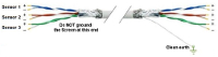
Sensor to microcontroller / data acquisition device cables

Accelerometers
IMU / Gyroscope
Magnetometer

Audio
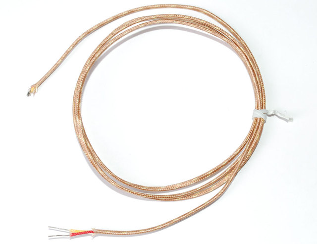
Thermocouple
AF Sensirion SHT40 Temperature & Humidity Sensor
.svg)
Motion Sensors
.png "object detection sensors")
Object Detection Sensors

Strain Gauge

Color
.png)
Pressure
Liquid Flow Meter

Operational Amplifiers
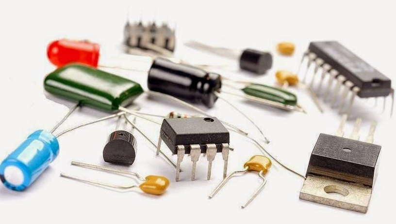
Components

Tools
Basic Components

Suppliers

VAC

XBee I/O Line Passing
xBee wireless communication modules + Arduino

I2C bus / SPI / 1-Wire
.png)
UART TTL Serial RS-232
.png)
LoRa Communications

Triac
Light Emitting Diode (LED)

NeoPixels
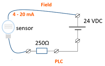
4-20 mA Current Loops
.png)
Human Health & Electrical Power
HMI
")
Mobile Apps
Hall Effect Sensor
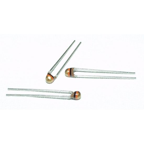
NTC Thermistor
.png "Op Amp - operational amplifier. Amplify, filter, add, manipulate analog signals.")
Amplify an Analog Signal

Offset a input signal
.png)
Electric Motors
.jpg)
Laptop 12V Power Supply

MCP2515 CAN Bus Module
TJA1050 CAN Bus Module

1.2" 4-Digit 7-Segment LED Display

Batteries

2022 Character Display Comparison
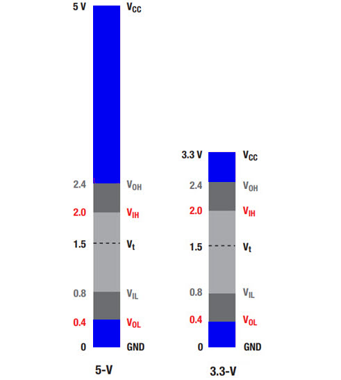
Logic Level Converter
.png)
Circuit Protection
Diodes
.jpg)
PMOS / P-Channel MOSFET

Logic Level NMOS / N-Channel MOSFET
Voltage Measurement

Analog to Digital Conversion (ADC)

Variable output VDC
.png)
Turn On/Off Noisy DC Device
ADC Analog Input