Motor/Stepper/Servo Shield
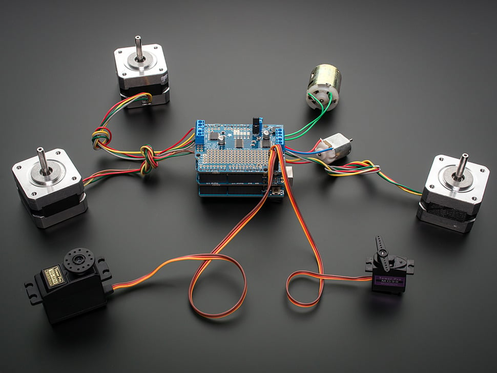
Adafruit Motor/Stepper/Servo Shield for Arduino v2 Kit - v2.3 PN 1438. Utilizes TB6612 MOSFET drivers with 1.2A per channel continuous current capability. A fully-dedicated PWM driver chip handles all the motor and speed controls over I2C. Only two GPIO pins required. 5x I2C adddress 0x60 to 0x80 select pins allow the use of up to 32 shields.
- 2 connections for 5V 'hobby' servos with high-resolution dedicated timer to avoid jitter
- 4 H-Bridges: TB6612 chipset provides 1.2A per bridge. 4.5 to 13.5 VDC motors
- Up to 4 bi-directional DC motors with individual 8-bit speed selection (so, about 0.5% resolution)
- Up to 2 stepper motors (unipolar or bipolar) with single coil, double coil, interleaved or micro-stepping.
- Supports unipolar (5-wire and 6-wire) and bipolar (4-wire) steppers (but not any other # of wires)
Adafruit Motor Shield tutorial
Adafruit Motor Selection Guide
5 - 12 VDC must be supplied to the motor shield. Too high a voltage can damage your controller and/or your motor. Current draw is determined by the motor. Choose one option:
- Connect the DC Barrel Jack OR USB cable to the stacked Arduino and install the VIN jumper on the shield next to the motor power in terminal block. Do not connect power to the motor power terminal port.
- Connect 5-12 VDC to the motor power terminal port and remove the VIN jumper. You may optionally use the USB cable to power the Arduino and program it, but do not connect power to the Arduino DC barrel jack.
If the Green LED next to the power terminal block isn't lit up brightly do not continue!
Motor phase resistance needs to be 10 ohms or more. "Phase resistance is the single most important detail for determining compatibility with simple H-Bridge drivers such as the ones used on the shield." At a low resistance of 3.5 to 4.0 ohms, a voltage of 4.2V is required to avoid overloading the driver chips, and that is right at the threshold. A motor with 35 ohm resistance can be driven with 12 V from the shield. You can measure the motor resistance between one pair of the motor leads.
Adafruit Motor Selection Table
DC Motors
Brushed DC motors are lightweight, have good low-speed torque, but are noisy. Speed and direction proportional to the voltage. PWM is typically used to control motor speed. An H-Bridge and a PWM pin is used for speed and direction (fwd/rev) control.
Brushless DC motors (BLDC) use electronic commutation to switch the current flow to drive the motor. They are very quiet, efficient, and used in high-precision servomechanisms.
Connect motors to M1 to M4. Motors are bi-directional so poloarity doesn't matter, but do not connect the motor to the GND terminal. The motor power requirements should be 5 VDC.
Stepper Motors
Stepper motors are DC motors that move in discrete steps. The provide precise positioning and speed control, excellent low-speed torque, fantastic 'holding torque' to maintain a position. Efficiency is low and an encoder or limit switch may be needed to establish a reference position. Current requirements are rated per phase, so multiply that requirement by 2x to get the total current requirement. They draw more current at slower speeds and reach a maximum current when they are stopped with 'holding current' applied. To reduce holding current when stopped, call the 'release' function to cut all power to the motor, or switch to 'SINGLE' stepping mode for the last step.
Stepper motors vary in physical size, and most have torque ratings. NEMA numbers define standard faceplate dimensions for mounting the motor (but nothing else).
Positioning resolution is expressed as degrees per step.
Stepper motors that can be driven with commonly available drivers are Permanent Magnet or Hybrid steppers, either 2-phase bipolar, or 4-phase unipolar. The shield supports unipolar (5-wire and 6-wire) and bipolar (4-wire) steppers (but not any other # of wires). Connect one stepper motors to a motor port without any other motor on that port. Connect the motor coil #1 (red & yellow) to the two M4 terminal screws, and coil #2 (green & gray) to the M3 terminal ports.
Stepper motors should be rated for 5 to 12 VDC.
Geared Motors
Gear trains can be mated to brushed or brushless DC motors as well as steppers. Friction, inertia, and backlash influence their performance.
Servo Motors
This motor employs negative feedback to control motor speed and/or position. Positioning accuracy and repeatability of +/- 1 degree is typical. The feedback mechanism to correct drift from the target position can cause jitter (use a stepper motor if this happens for an application).
RC Servos typically provide position control over an approximately 180 degree range. All feedback goes to an internal controller and is not accessible externally.
Analog Feedback Servos have an extra feedback connection you can read with an analog input. Analog Feedback Servos Guide
A Continuous Rotation Servo are technically not a servo. They are a miniature self-contained reversible, speed controlled gear-motor with continuous (360 °) rotation. Good for applications where a compact DC gearmotor with built-in H-Bridge driver is needed. Adafruit Modifying Servos for Continuous Rotation
Motor Controllers
Brushed DC Motor Control
PWM is typically used to control motor speed. An H-Bridge and a PWM pin is used for speed and direction (fwd/rev) control. The Adafruit Motor Shield V2 handles all the PWM speed control.
Brushless DC Motor Control
ESC (Electronic Speed Controls) for brushless RC motors are rated by amps. Add a 10 to 20% saftey factor to the motor rating.
Stepper Motor Control
Two complete H-bridgets and 2 channels of PWM are required to control the motor.
Troubleshooting
Reduce brushed motor noise by adding 10 nF capacitors between the motor case and each power connection terminal.
Software
Stepping modes. SINGLE is the weakest, DOUBLE is the strongest, INTERLEAVE is a good compromise.
Do you need help developing or customizing a IoT product for your needs? Send me an email requesting a free one hour phone / web share consultation.
The information presented on this website is for the author's use only. Use of this information by anyone other than the author is offered as guidelines and non-professional advice only. No liability is assumed by the author or this web site.


