Arduino Project
Jan 2020
Arduino XBee Fireplace Remote
The remote for our propane fireplace/stove stopped working. The receiving unit at the fireplace ran on batteries, so they frequently needed replacement. A new remote would cost $150 to $200, so I decided to make my own replacement with a few additional enhancements.
Functional Requirements
- 110 VAC powered (no batteries!), both the remote and receiver.
- Simple on/off latching pushbutton at remote and receiver with visual indication of on/off status.
- Rotary encoder to adjust setpoint temperature on remote.
- Visual indication of when fireplace has been commanded on/off at remote and receiver
- Display of current temperature (and optionally humidity) at remote.
- Adjustment to fine tune the Proportional Integral Derivative (PID) .
- Off delay timer on remote automatically activated when it is turned on, set for four hours (prevents stove from staying on all night when someone forgets to turn it off, a frequent issue).
A Note About The Gas Valve Electronic Interface
The most common control valve used on both ventless and vented gas log fireplace/stove models is the millivolt valve. You can identify a millivolt gas valve is by its three electrical terminals located on the side of the valve, labeled TPH - TP - TH. A connection (jumper / switch) across the TPH and TH terminals will activate the furnace (fire on) when closed, and turn it off when open. Our furnace has a manual on/off switch in parallel to this connection, so that the furnace may be used when the remote is not working (or no remote switch implemented). Note that if using a remote or other parallel switch and you intend for that remote switch to control the on/off of the fireplace flame, then you need to turn the manual switch on the furnace off. Temperature is controlled by digitally turning the flame on until the desired temperature is reached, and then off. The flame height and fan circulation is not adjustable in our situation (typical for most units).
Product Design
The functional requirements suggested I could use a pair of XBees configured for 'I/O Line Passing' mode in order to accomplish the task. This virtually links the XBee inputs and outputs, such that setting the digital input on the 'Sender' XBee will result in the same HIGH/LOW output on the 'Receiver' XBee located at the stove. A relay connected to the receiver XBee and the gas stove TPTH and TH connections provides a simple (isolated) way of providing the flame on/off command.
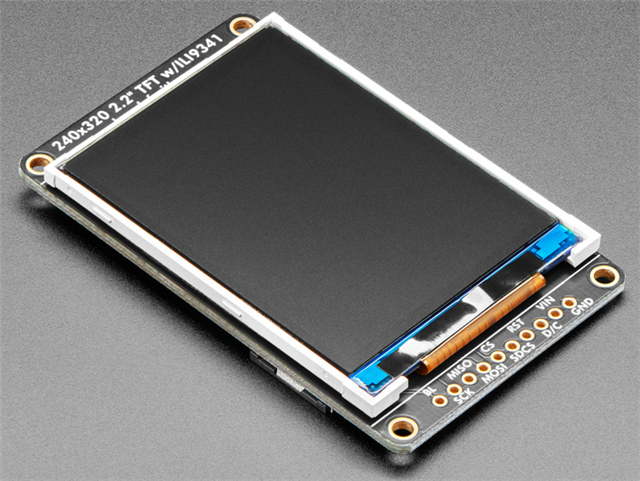
I wanted to use an existing display that I already had for this project. The requirement however, it that it needed to support 3.3 V logic in order to interface with the Arduino Fio. The display I setteled on was an Adafruit ST7565 RGB. I configured the display to simply show the ambient and setpoint temperatures in the largest font that I could fit on the screen.
XBee
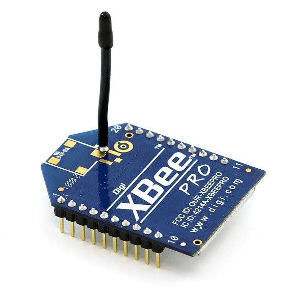
The XBee model I used was the XBee Pro 60mW Wire Antenna - Series 1 (802.15.4). This popular 2.4GHz XBee XBP24-AWI-001 module from Digi has the same pinout and command set of the basic series, with an increase output power of 60mW, resulting in a range of 1 mile (instead of 300 ft). It far exceeds the requirements for this project, but I had a pair on hand and decided to use them.
I decided to use the periodic sampling method of I/O Line Passing between the two XBees. The settings I implemented are shown in the table below. The Sender periodically samples enabled digital inputs (IR=0x64 = 10 Hz) and sends out packets over the network. When the Receiver receives a packet, (DL=0x4141), it's digital outputs are updated to match the sender because it's I/O Output Enable setting is disabled (IU=0), and the IA I/O Input Address is set to allow any received I/O packet to change outputs (IA=0xFFFF). The DIO timers were set to timeout at 0x4650 (18000 * 100 ms = 1800000 ms = 30 minutes).
The Sender periodically samples enabled digital inputs (IR=0x64 = 10 Hz) and sends out packets over the network. Changes to the Sender's inputs do NOT trigger a packet transmit (IC=0x0). When the Receiver receives a packet, (DL=0x4141), it's digital outputs are updated to match the sender because it's I/O Output Enable setting is disabled (IU=0), and the IA I/O Input Address is set to allow any received I/O packet to change outputs (IA=0xFFFF). Note that if the Sender XBee stops sending packets (because it's power is lost), then the Receiver XBee will stop asserting the output for DO3 after 25.5 seconds.
| Sender | Receiver | |
|---|---|---|
| CH | 0xC | 0xC |
| PAN ID | 0x3334 | 0x3334 |
| DH Destination High | 0x0000 | 0x0000 |
| DL Destination Low | 0x4141 | 0x1818 |
| MY Address | 0x1818 | 0x4141 |
| CE Coordinator Enable | 0x1 (coordinator) |
0x0 (EndUser) |
| AP Mode (1) | AP=0x0 | AP=0x0 |
| DIO 3 (pin 17) | DI3 | DO3 LOW |
| DIO 4 (pin 18) | DI2 | DO2 LOW |
| IR Sample Rate | IR=0x64 (1) | IR=0x0 (disable) |
| IC DIO Change Detect | IC=0x0 (disable) | IC=0x0 (disable) |
| IA I/O Input Address | IA=0xFF (disable) | IA=0x1818 (2) |
| IU I/O Output Enable | IU=0x0 (disable) | IU=0x0 (disable) |
| T2 D2 Output Timeout | 0x4650 (30 min) | |
| T3 D3 Output Timeout | 0x4650 (30 min) |
Arduino Fio
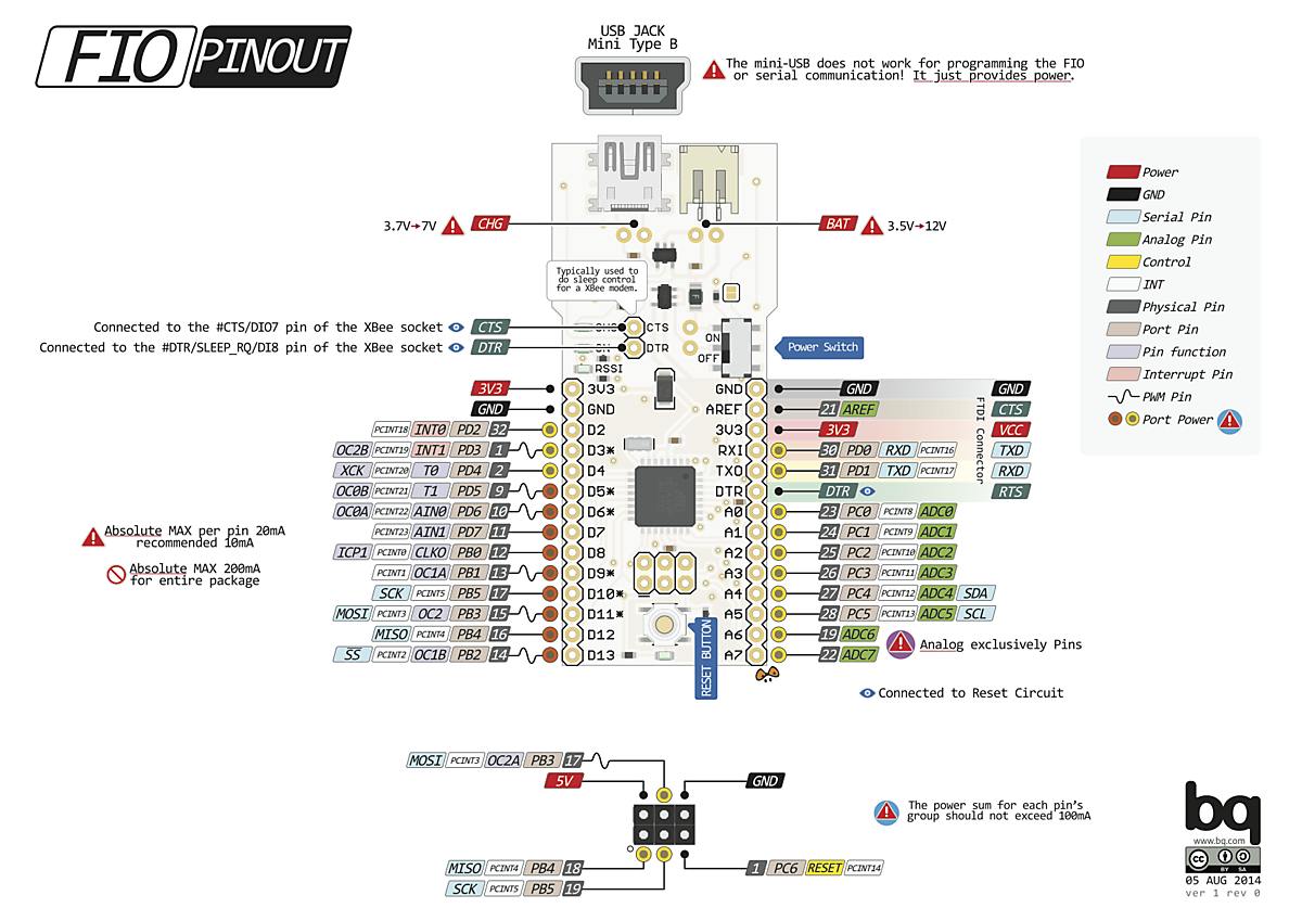
The Fio Tutorial The Fio is designed to provide a simple interface between the Arduino (Fio) and XBee. A few of the XBee pins are wired to the Fio, including the serial interfaces (the XBee DOUT pin is connected to the Fio Rx pin, and the XBee DIN is connected to the Fio Tx pin).
I didn't need to use the serial communication built into the Fio and the XBee socket on the Fio board (because I was using I/O line passing), so I completely ignored that and simply configured an analog pin on the Fio for digital output and connected that to a digital input pin on the XBee. The XBee was mounted separately from the Fio (i.e. not on the Fio XBee socket) for my project and therfore not as shown below.
| Fio | Component |
|---|---|
| A1 | XBee DI2 (pin 18) |
| D8 to D12 | ST7565 RGB display |
| D10, D11, D12 | Rotary Encoder |
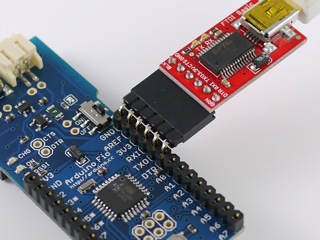
Uploading software to the Fio is performed through a FTDI adapter, as shown in the image below. Make sure the pins are properly aligned!
Printed Circuit Boards
I used Fritzing to design the initial breadboard connections for the 'Sender' and the 'Receiver', and then converted them into a printed circuit board (PCB) design using Fritzing. Later I had the PCB fabricated by JLPCB at a fantastic cost of $4 per design + shipping (minimum order is five PCB's and cost for five is $4 plus shipping).
Sender breadboard, PCB design, fabricated PCB
Receiver Fabricated & Assembled PCB (XBee not installed)
SolidWorks design of the enclosure
Additional Resources
Get Started with XBee – A Beginner’s Tutorial
XBee Manual (courtesy SparkFun)
XBee 802.15.4 Digital Input/Output Line Passing
Sparkfun XBee Shield Hookup Guide
Rob Faludi - Common XBee Mistakes
Do you need help developing or customizing a IoT product for your needs? Send me an email requesting a free one hour phone / web share consultation.
The information presented on this website is for the author's use only. Use of this information by anyone other than the author is offered as guidelines and non-professional advice only. No liability is assumed by the author or this web site.

.png)
